|
|
|
Initialization |
-
Pre-initialization
-

-
Image shows a snapshot from "LL_USB.vi"
This function always returns true, so there is nothing to connect
- uInt8 SP_DisableDialog(void)
-
Prevents DLL from displaying a dialog box used for runtime messaging
as well as handling of USB device connect/disconnect system messages.
ActiveX, LabView, and some other application interfaces have problems with
the Dialog's resources occupying their program space and will crash on exit
if the Dialog box is used. ALWAYS call this function FIRST THING when
the program first starts if you need to make use of it with your
application.
-
Arguments
-
Return type:
- 8-bit. 1 (true) = success, 0 (false) = failed
-
Arguments
back to "Table of Contents"
back to "List of all function calls"
-
Initialization
-
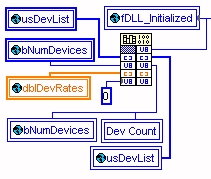
- Image shows a snapshot from "LL_USB.vi"
-
uInt8 SP_InitAllDevices(
- uInt16 *pausDevList, uInt8 *pbNumDevices, double *padblRate, uInt8 fShowDevList);
-
This call is used to initialize all devices. Unlike typical serial devices, USB
type devices require an enumeration process, followed by each device being
initialized to set it to certain configuration parameters. Place all of the device
IDs that you wish to initialize in the array pointed to by pDevList. The number
of devices is limited to 32. The DLL will attempt to initialize whichever IDs
are in that list. Any devices that fail to initialize will be removed from the list.
On return, the list will contain only valid device ID's that initialized properly.
If scanning, do not place the devices that are currently scanning in the list since the DLL will automatically attempt to close and reenumerate any device that is currently in the list including the ones that are scanning if they are in the list.
-
Arguments
pausDevList:
- Pointer to a 32-member array of 32-bit integer data types representing the LL_USB devices that you wish to intitialize.
-
pbNumDevices:
- Pointer to an 8-bit data type (BYTE). The DLL will set this to the number of valid devices that it found from the pDevList array described above.
-
padblRate:
- Pointer to a 32-member array of 64-bit double data types representing the rates for the LL_USB devices that you wish to intitialize. The offsets in the array of each rate should correspond with the offsets of the appropriate DeviceID in the pDevList array described above. When the call returns the pDevList array described above and this array will have only valid entries in them. The DLL will reorganize the arrays if any of the desired devices failed to initialize so that there are no "holes" in the arrays. The corresponding alignment of the two arrays will be maintained.
-
fShowDevList:
- This is an 8-bit data type used as a flag to let the DLL know if you'd like it do display the devce lists during the init process. It is recommended to set this flag to 0 except for special trouble shooting circumstances. When this flag is set, the DLL will display Windows style message boxes showing the device ID lists as it sees them during various stages of the initialization process.
-
Return type:
- 8-bit. 1 (true) = success, 0 (false) = failed
-
Arguments
back to "Table of Contents"
back to "function calls by category"
back to "List of all function calls"
-
Device rate and calibration
-
- Changing rate
- Changing rate
-
-
uInt8 SP_SendRate(
- double* pdblRate, uInt16 usDevID);
-
This call is used to change the rate of a device.
If scanning, do not place the devices that are currently scanning in the list
since the DLL will automatically attempt to close and reenumerate any
device that is currently in the list including the ones that are scanning if they
are in the list.
-
Arguments
pdblRate:
- Pointer to a 64 bit data variable. This is the rate that the DLL will attempt to set the device to. Due to certain limitations of the device all rates aren't valid and may be adjusted slightly by the DLL. For example, a requested rate of 1000Hz may be altered to 1000.7Hz. The value pointed to by dblRate will be set to the actual rate that the device was set to.
-
Return type:
- 8-bit. 1 (true) = success, 0 (false) = failed
-
Arguments
-
uInt8 SP_SendRate(
-
System calibration
-
-
uInt8 SP_SystemCalibration(
- uInt16 usDevID, uInt8 bCurChan);
- uInt16 usDevID, uInt8 bCurChan);
-
This call is used to change the rate of a device.
If scanning, do not place the devices that are currently scanning in the list
since the DLL will automatically attempt to close and reenumerate any
device that is currently in the list including the ones that are scanning if they
are in the list.
-
Arguments
usDevID:
- 16-bit data variable representing the device that you wish to calibrate.
-
bCurChan:
- 8-bit data type representing the current channel the device listed above is set to. The DLL needs to do channel changes during the system calibration process. Passing it this parameter allows it to return the channel to the original setting before returning.
-
Return type:
- 8-bit. 1 (true) = success, 0 (false) = failed
-
Arguments
back to "Table of Contents"
back to "function calls by category"
back to "List of all function calls"
-
uInt8 SP_SystemCalibration(
back to "Table of Contents"
back to "function calls by category"
back to "List of all function calls"
|
Basic I/O |
-
change channel
-
-
uInt8 SP_SendChan(
- uInt16 usDevID, uInt8 bCurChan, uInt8* pbReserved);
- uInt16 usDevID, uInt8 bCurChan, uInt8* pbReserved);
-
This call is used to change the active channel of a device. It can be used
anytime once the device has been initialized.
Valid channels for a Model-301 are 0,1,6,7 and for a Model-302 are 0-7. During multi-channel scan mode (explained elsewhere in this document), the channel changes are ignored. Channel 7 is concidered the "offset" channel and channel 6 is concidered the "full-scale" channel.
-
Arguments
usDevID:
- 16-bit data variable representing the device that you wish to send channel change to.
-
bCurChan:
- 8-bit data type representing the current channel the device listed above is to be set to.
-
pbReserved:
- Pointer to an 8-bit data variable. This is currently reserved for future use.
-
Return type:
- 8-bit. 1 (true) = success, 0 (false) = failed
-
Arguments
-
uInt8 SP_SendChan(
-
send analog output
(Model 302 only)
-
-
uInt8 SP_SendDAC(
- USHORT uInt16, double dblVoltage, uInt8 bDAC, uInt8* pbReserved);
- USHORT uInt16, double dblVoltage, uInt8 bDAC, uInt8* pbReserved);
-
This call is used to send an analog voltage to a Model 302.
-
Arguments
usDevID:
- 16-bit data variable representing the device that you wish to send analog data to.
-
dblVoltage:
- Voltage to send to Model-302
-
bDAC:
- 8-bit data variable that represents the channel to send the analog voltage to
-
pbReserved:
- Pointer to an 8-bit data variable. This is currently reserved for future use.
-
Return type:
- 8-bit. 1 (true) = success, 0 (false) = failed
-
Arguments
-
uInt8 SP_SendDAC(
-
send digital output
-
-
uInt8 SP_SendDigOut(
- uInt16 usDevID, uInt8 bDigOut, uInt8* pbReserved);
- uInt16 usDevID, uInt8 bDigOut, uInt8* pbReserved);
-
This call is used to send a digital output value to the device. It can be used
anytime once the device has been initialized. Valid digital output values are
0-255.
-
Arguments
usDevID:
- 16-bit data variable representing the device that you wish to send channel change to.
-
bDigOut:
- 8-bit data variable that the current channel the device listed above is set to. The DLL needs to do channel changes during the system calibration process. Passing it this parameter allows it to return the channel to the original setting before returning.
-
pbReserved:
- Pointer to an 8-bit data variable. This is currently reserved for future use.
-
Return type:
- 8-bit. 1 (true) = success, 0 (false) = failed
-
Arguments
-
uInt8 SP_SendDigOut(
-
read digital input
-
-
The digital input value is automatically returned whenever the device is read. It's recommend to use one of the functions listed below to retrieve the digital input value and then throw away any unneeded return values that the function call returns. Both are explained just a little further down within this documentation.
-
SP_ReadWriteOneDevice()
-
SP_GetOneConversion()
-
SP_ReadWriteOneDevice()
back to "Table of Contents"
back to "function calls by category"
-
direct read/write of device
-
The following table shows a function call that will probably
not be needed by developers using nothing except newer "SP_"
style function calls throughout their application. The followoing
is just a newer version of the old "SP_ReadWriteOneDevice()"
function call which is prototyped elsewhere in this documentation.
-
uInt8 SP_ReadWriteOneDevice(
- uInt8 fReadWrite, uInt8* pabDynamicDataArray,
uInt16 usDevID, uInt32* puiNumBytes, uInt8* pbDigIn,
uInt8 bCurChan, uInt32* puiFlags);
- uInt8 fReadWrite, uInt8* pabDynamicDataArray,
-
Use this function call to read or write directly to the device.
-
Arguments
fReadWrite:
- 8-bit data variable that indicates whether the request is for a READ(1) or a WRITE(0)
-
pabDynamicDataArray:
- This argument is a pointer to an array of 8-bit data either to be written to or read from depending on the value of the "fReadWrite" variable. If doing a READ request then the array must be large enough to hold 32 bytes of data. If doing a WRITE request, then the array is to contain the 8 bytes of data to be written to the device. Although much of the data used in the read and write is made use of for many of the read/write operations, the array must still be sized to the full size as just mentioned.
-
usDevID:
- 16-bit data variable representing the device that you wish to calibrate.
-
puiNumBytes:
- Pointer to a 32-bit data variable. The DLL will set this value to the number of bytes that was either written or read from the device.
-
pbDigIn:
- Pointer to an 8-bit data variable. The DLL will set this value to the current digital input value. The DLL reads the digital input every time that it reads the device.
-
bCurChan:
- An 8-bit data variable containing the current channel the device is set to. If an I/O error occurs during the call, the DLL will attempt to recover from the error. Depending on the severity of the error, the currently selected channel could be lost and required resetting by the DLL.
-
puiFlags:
-
Pointer to a 32-bit data variable. The DLL uses the various bits of this
variable to let the application know the status of the device including
any errors that occured while trying to read/write to the device. If the
variable is zero when the call returns, then there were no errors. If it's
not zero then the bits as described in the table below indicates the current
condition of the device.
Even though the "PWR_NO_RESET_REQUIRED" is not set by the DLL in this function call when there are no errors, the developer can assume that the device has power. We leave this bit unset in this call when there are no errors to make it easier for the developer to trap for a non-zero return value rather than having to do a specific bit-test even though no errors occured. This bit flag is also used by other function calls that checks the current status of the devices. -
PWR_NO_RESET_REQUIRED 0x1 PWR_NO_DEVICE 0x2 PWR_RESET_PIPE_FAILED 0x4 PWR_RESET_PIPE_SUCCESS 0x8 PWR_RESET_DEV_FAILED 0x10 PWR_RESET_DEV_SUCCESS 0x20 PWR_NO_POWER 0x40 PWR_YES_POWER 0x80 -
Return type:
- 8-bit. 1 (true) = success, 0 (false) = failed
-
Arguments
back to "Table of Contents"
back to "function calls by category"
back to "List of all function calls"
-
uInt8 SP_ReadWriteOneDevice(
back to "Table of Contents"
back to "function calls by category"
back to "List of all function calls"
back to "Table of Contents"
back to "function calls by category"
back to "List of all function calls"
back to "Table of Contents"
back to "function calls by category"
back to "List of all function calls"
|
Polled data mode |
-
get one conversion
-
-
uInt8 SP_GetOneConversion(
- uInt16 usDevID, uInt32* uiConvRawCount,
uInt8 bCurChan, uInt8* pbDigIn);
- uInt16 usDevID, uInt32* uiConvRawCount,
-
This call is used to read a single conversion from the device.
-
Arguments
usDevID:
- 16-bit data variable representing the device that you wish to send channel change to.
-
uiConvRawCount:
-
Pointer to a 32-bit variable to contain the 24-bit data returned by
the device. We return this as as 24-bit data rather than attempt to convert
it to a voltage within the DLL since some programmers prefer to set their
own voltage range to apply to the 24-bit data rather than use a standard
+-5 Volts.
An example of converting the 24-bit data returned above to a range of +-5 volts is shown below:-
INT iCntTemp = uiConvRawCount;
DOUBLE Voltage = (iCntTemp - 8388608) * 0.00000059604645
-
bCurChan:
- An 8-bit data variable containing the current channel the device is set to. If an I/O error occurs during the call, the DLL will attempt to recover from the error. Depending on the severity of the error, the currently selected channel could be lost and required resetting by the DLL.
-
pbDigIn:
- Pointer to an 8-bit data variable. The DLL will set this value to the current digital input value. The DLL reads the digital input every time that it reads the device.
-
Return type:
- 8-bit. 1 (true) = success, 0 (false) = failed
-
Arguments
-
-
Special note:
- If this call returns zero that could indicate a variety of error conditions such as the power or USB cable being disconnected. To find out the cause of the problem, we recommend calling SP_CheckPower() described elsewhere in this document. This call also has a self-recovery mechanism built in to recover from certain errors.
-
Special note:
back to "Table of Contents"
back to "function calls by category"
back to "List of all function calls"
-
uInt8 SP_GetOneConversion(
-
scanning
-
start scan ( LabView )
-
Starts scanning a device.The following is designed
specifically for development languages such as LabView that make it difficult
to pass structured data of various sizes to a function within a DLL. Such
languages require incoding such data in to similiar data types and then passing
it within an array which is then decoded by the DLL.
-
uInt8 SP_StartScan(
- uInt16 usDevID, double* padblScanObject);
- uInt16 usDevID, double* padblScanObject);
-
This call is used to place a device into scan mode. If this call returns success
then the device will be in scan mode and you can begin reading the data from the
device using the function calls explained below and elsewhere within this document.
-
Arguments
usDevID:
- 16-bit data variable representing the device that you wish to send channel change to.
-
padblScanObject:
- Pointer to an array of structured data. Each member of the structured data is cast as a double data type, placed into the array by the calling application, and then passed to the DLL. The DLL decodes the array for usage, and then recodes it before returning to the calling app. To see an example of the array's data and more information concerning the LabView ScanObject Array follow the link.
-
Return type:
- 8-bit. 1 (true) = success, 0 (false) = failed
-
Arguments
-
uInt8 SP_StartScan(
-
read scan data ( LabView )
-
Reads the scan data from a non-digital input type scan The following is designed
specifically for development languages such as LabView that make it difficult
to pass structured data of various sizes to a function within a DLL. Such
languages require incoding such data in to similiar data types and then passing
it within an array which is then decoded by the DLL.
-
uInt8 SP_ReadScanData(
- uInt16 usDevID, uInt16 usNumPointsToRead, uInt32* pauiDataBuff, double* padblScanObject);
- uInt16 usDevID, uInt16 usNumPointsToRead, uInt32* pauiDataBuff, double* padblScanObject);
-
This call is used to read scan data from a device. It's designed with
the "LabView" development environment in mind.
-
Arguments
usDevID:
- 16-bit data variable representing the device that you wish to read scan data from.
-
usNumPointsToRead:
-
This is an 16-bit value that is set by the Application. This value should
be set to the number of points that you wish to read with the call. This
value must always be divisible by the total number of channels being
scanned, which is also the minimum value that you set it to, with one
exception:
It is recommended that you do not ask for a very large number of points (large number of packets) with each read. The reason is due to time slicing issues. If you make "usNumPointsToRead" and make the call, the DLL could take a long time to extract the data from it's buffer and make the transfer to your buffer before returning which could make your application appear to be "hung". If you see that you are falling behind in the buffer (SO_PointsInBuffer grows increasing large) it is better to make many consecutive calls to this function rather than try and ask for all the available data at once since that will allow your application a time slice between calls to handle any pending events (such as mouse movement etc).- If you'd like to know how many points are available, you can set this value to 0 and make the call and then when you return, the SO_PointsInBuffer member of your ScanObject struct will contain the number of points available to be read. You can then make that value divisible by the total number of channels and repeat the call with the new request for the number of points you've just calculated.
-
pauiDataBuff:
-
Pointer to an array of 32-bit data.
NOTE: Please see "DLL_ReadScanData_DIO()" above for complete description of how the data is organized within this buffer.
-
padblScanObject:
- Pointer to an array of structured data. Each member of the structured data is cast as a double data type, placed into the array by the calling application, and then passed to the DLL. The DLL decodes the array for usage, and then recodes it before returning to the calling app. To see an example of the array's data and more information concerning the LabView ScanObject Array follow the link.
-
bReserved:
- 8-bit data variable. This is currently reserved for future use.
-
Return type:
- 8-bit. 1 (true) = success, 0 (false) = failed
-
Arguments
back to "Table of Contents"
back to "function calls by category"
back to "List of all function calls"
-
uInt8 SP_ReadScanData(
-
read scan data with digital input ( LabView )
-
Reads the scan data from a digital input type scan The following is designed
specifically for development languages such as LabView that make it difficult
to pass structured data of various sizes to a function within a DLL. Such
languages require incoding such data in to similiar data types and then passing
it within an array which is then decoded by the DLL.
-
uInt8 SP_ReadScanDataWithDigin(
- uInt16 usDevID, uInt32* pauiDataBuff, uInt8* pabDiginBuff,
uInt8 pbCurChan, uInt16 usNumPointsToRead, double* padblScanObject);
- uInt16 usDevID, uInt32* pauiDataBuff, uInt8* pabDiginBuff,
-
This call is used to read scan data from a device. It's designed with
the "LabView" development environment in mind.
-
Arguments
usDevID:
- 16-bit data variable representing the device that you wish to read scan data from.
-
pauiDataBuff:
-
Pointer to an array of 32-bit data. Each member of the this array contains
the 24-bit data that corresponds with the 8-bit digital input value read by the
device. When the device has been set to use this scanning mode, it will read
the digital input each time it reads a point from the A/D converter. It
will place the 24-bit data into this array and the 8-bit digital input in
the pabDiginBuff at the same offsets. When reading the data from this array,
use the same offset to read the data from the pabDiginBuff array.
This type of scan is most useful for using the digital input value to trigger
on, or mark certain data points as corresponding with certain digital input
values.
Model-301
( MULTI_CHAN_DIGIN_SCAN )
The following table shows how the buffers will look for a scan that includes 4 channels. Note that a Model-301 only has 4 channels: 0,1,6, and 7. Channel 6 is the full scale channel and 7 is the offset channel.first row shows data, second shows digital input pauiDataBuff (24-bit data) channel 0 channel 1 channel 6 channel 7 pabDiginBuff (8-bit digital input) channel 0 channel 1 channel 6 channel 7
Model-302
( MULTI_CHAN_DIGIN_SCAN )
The following table shows how the buffers will look for a scan that includes 4 channels. Note that a Model-302 can scan up to 8 channels and that all channels are scanned sequentially.first row shows data, second shows digital input pauiDataBuff (24-bit data) channel 0 channel 1 channel 2 channel 3 pabDiginBuff (8-bit digital input) channel 0 channel 1 channel 2 channel 3
Model-302
showing digital-input-calibration type scan
( MULTI_CHAN_CAL_DIGIN_SCAN )
The following table shows how the buffers will look for a scan that includes 4 channels. Note that a Model-302 can scan up to 8 channels and that all channels are scanned sequentially.first row shows data, second shows digital input pauiDataBuff (24-bit data) channel 0 channel 1 channel 2 channel 3 channel 7 (offset) pabDiginBuff (8-bit digital input) channel 0 channel 1 channel 2 channel 3 channel 7 (offset)
Model-302
showing digital-input-calibration type scan with multiple-packets
( MULTI_CHAN_CAL_DIGIN_SCAN )
The following table shows how the buffers will look for a scan that includes 2 channels, except this time we'll ask for 3 packets - that means that usNumPointsToRead will be set to 9. I'll condense the table a little bit so it will all fit, so just look at the tables above for better descriptions of the actual labels if you need to. The two examples above show what the buffers will look like if you only ask for one packet (all the data for all channels). The table below shows how the buffers will look when you ask for multiple packets. Asking for larger packets is fine, but it's very important that the value you set "usNumPointsToRead" is divisable by the number of channels that you're scanning. Be sure to include the calibration channel in that count. Since the calibration channel is actually one of the active channels, please note that a 6 channel scan and a 7 channel scan will both return 7 channels since the offset channel is automatically returned with that type of scan.first row shows data, second shows digital input |----- first packet -----| |----- second packet -----| |----- third packet -----| Data ch 0 ch 1 ch 7 ch 0 ch 1 ch 7 ch 0 ch 1 ch 7 Digin ch 0 ch 1 ch 7 ch 0 ch 1 ch 7 ch 0 ch 1 ch 7
-
pabDiginBuff
-
Pointer to an array of 8-bit data.
NOTE: Please see table above for complete description of how the data is organized within this buffer. -
pbCurChan:
-
padblScanObject:
- Pointer to an array of structured data. Each member of the structured data is cast as a double data type, placed into the array by the calling application, and then passed to the DLL. The DLL decodes the array for usage, and then recodes it before returning to the calling app. To see an example of the array's data and more information concerning the LabView ScanObject Array follow the link.
-
bReserved:
- 8-bit data variable. This is currently reserved for future use.
-
Return type:
- 8-bit. 1 (true) = success, 0 (false) = failed
-
Arguments
back to "Table of Contents"
back to "function calls by category"
back to "List of all function calls"
-
uInt8 SP_ReadScanDataWithDigin(
-
write while scanning
-
This is the recommended function call for writing while in scanning mode.
-
uInt8 SP_WriteWhileScanning(
- uInt16 usDevID, uInt8 bCmnd, uInt8 bArg, uInt32* puiCurWriteStat);
- uInt16 usDevID, uInt8 bCmnd, uInt8 bArg, uInt32* puiCurWriteStat);
-
This function writes the command token (bCmnd) and argument (bArg) to the device
while in scanning mode.
-
Arguments
usDevID:
- 16-bit data variable representing the device that you wish to read scan data from
-
bCmnd:
- 8-bit data type representing the command token to be written to the device, for example "0x02" for writing a digital output NOTE: only digital output command token is currently recommended.
-
bArg:
-
8-bit data type representing the argument to the command toke to be written to the
device, for example "0-255"
NOTE: only argument to digital output command token is currently recommended. -
Return type:
- 8-bit. 1 (true) = success, 0 (false) = failed
-
Arguments
-
uInt8 SP_WriteWhileScanning(
-
end scan
-
This is the recommended function call for taking the device out of scanning mode.
-
uInt8 SP_EndScan(
- uInt16 usDevID);
- uInt16 usDevID);
-
This function takes the device out of scanning mode and must be called to
terminate a scan. If you are scanning, you must always call this function
before exiting your application or reinitializing the scanning device.
-
Arguments
usDevID:
- 16-bit data variable representing the device that you wish to read scan data from
-
Return type:
- 8-bit. 1 (true) = success, 0 (false) = failed
-
Arguments
-
uInt8 SP_EndScan(
back to "Table of Contents"
back to "function calls by category"
back to "List of all function calls"
back to "Table of Contents"
back to "function calls by category"
back to "List of all function calls"
back to "Table of Contents"
back to "function calls by category"
back to "List of all function calls"
|
Miscellaneous functions |
-
Get device status
(single device)
-
-
uInt8 SP_GetDevStat(
- uInt16 usDevID, uInt32* puiDevStat);
-
This call is used to get the current status of a multiple devices. It will
determine it the USB cable is connected and if the device is enumerated and
ready to be read or written to.
-
Arguments
usDevID:
- 16-bit data variable representing the device that you wish to check the status of.
-
puiDevStat:
-
The following table shows the possible values that the DLL will set the variable
pointed to by puiDevStat, indicating the status of the device.
DEV_NOT_FOUND 0x0 DEV_FOUND 0x1 DEV_DISCONNECTED 0x2 DEV_ENUMERATED 0x4 DEV_READY 0x8 DEV_OWNED_BY_ANOTHER 0x10 DEV_UNKNOWN_ERR 0x20 -
Return type:
- 8-bit. 1 (true) = success, 0 (false) = failed
-
Arguments
-
uInt8 SP_GetDevStat(
back to "Table of Contents"
back to "function calls by category"
back to "List of all function calls"
-
get device status
(multiple devices)
-
-
uInt8 SP_GetDevStatEx(
- uInt32* puiaDevStat, uInt16* pausAllDevList, uInt8* pbNumDevices);
-
This call is used to get the current status of a multiple devices. It will
determine it the USB cable is connected and if the device is enumerated and
ready to be read or written to.
-
Arguments
puiaDevStat:
-
Pointer to a 32-member 32-bit array which you should pre-initialize to
all zeros. The DLL will check the status of all devices listed in the
"pausAllDevList" array and set the corresponding index within the
array pointed to by this variable to the status of that device. The following
table shows the possible status of a device.
DEV_NOT_FOUND 0x0 DEV_FOUND 0x1 DEV_DISCONNECTED 0x2 DEV_ENUMERATED 0x4 DEV_READY 0x8 DEV_OWNED_BY_ANOTHER 0x10 DEV_UNKNOWN_ERR 0x20 -
pausAllDevList:
- Pointer to a 32-member array of the 16-bit data that represent the devices that you wish to determine the status of. Pleas be sure to put only devices for which you wan the status checked in this list and set the unused indexes to zero.
-
pbNumDevices:
- Pointer to an 8-bit byte type variable that the DLL will set to the total number of valid devices that it finds.
-
Return type:
- 8-bit. 1 (true) = success, 0 (false) = failed
-
Arguments
-
uInt8 SP_GetDevStatEx(
back to "Table of Contents"
back to "function calls by category"
back to "List of all function calls"
-
check device power
-
-
uInt8 SP_CheckPower(
- uInt16 usDevID, uInt8 bCurChan, uInt8* pbDigin, uInt32* puiFlags);
-
This call is used to determine if the main power cable is connected to the device.
The main power cable controls the actual A/D converter while the USB cable supplies
power to the portion of the hardware used to communicate with the device driver.
If the main power is disconnected, communication to the hardware will not be lost,
but A/D conversion will no longer be possible until the power is restored. If the
power was disconnected prior to this call but has been reconnected, this call will
attempt to reinitialize the A/D converter by attempting to retrieve on data point.
-
Arguments
usDevID:
- 16-bit data variable representing the device that you wish to check the power for.
-
bCurChan:
- An 8-bit data variable containing the current channel the device is set to. If an I/O error occurs during the call, the DLL will attempt to recover from the error. Depending on the severity of the error, the currently selected channel could be lost and required resetting by the DLL.
-
puiNumBytes:
- Pointer to a 32-bit data variable. The DLL will set this value to the number of bytes that was either written or read from the device.
-
pbDigIn:
- Pointer to an 8-bit data variable. The DLL will set this value to the current digital input value. The DLL reads the digital input every time that it reads the device.
-
puiFlags:
-
Pointer to a 32-bit data variable. The DLL uses the various bits of this
variable to let the application know the status of the device including
any errors that occured while trying to read/write to the device. If the
variable is zero when the call returns, then there were no errors. If it's
not zero then the bits as described in the table below indicates the current
condition of the device.
Even though the "PWR_NO_RESET_REQUIRED" is not set by the DLL in this function call when there are no errors, the developer can assume that the device has power. We leave this bit unset in this call when there are no errors to make it easier for the developer to trap for a non-zero return value rather than having to do a specific bit-test even though no errors occured. This bit flag is also used by other function calls that checks the current status of the devices.
PWR_NO_RESET_REQUIRED 0x1 PWR_NO_DEVICE 0x2 PWR_RESET_PIPE_FAILED 0x4 PWR_RESET_PIPE_SUCCESS 0x8 PWR_RESET_DEV_FAILED 0x10 PWR_RESET_DEV_SUCCESS 0x20 PWR_NO_POWER 0x40 PWR_YES_POWER 0x80 -
Arguments
-
pausAllDevList:
- Pointer to a 32-member array of the 16-bit data that represent the devices that you wish to determine the status of. Pleas be sure to put only devices for which you wan the status checked in this list and set the unused indexes to zero.
-
pbNumDevices:
- Pointer to an 8-bit byte type variable that the DLL will set to the total number of valid devices that it finds.
-
Return type:
- 8-bit. 1 (true) = success, 0 (false) = failed
-
uInt8 SP_CheckPower(
back to "Table of Contents"
back to "function calls by category"
back to "List of all function calls"
-
reset a device
-
-
uInt8 SP_SendReset(
- uInt16 usDevID, uInt8 bCurChan, uInt8* pbDigin, uInt32* puiFlags);
-
This call is used to get the current status of a multiple devices.
-
Arguments
usDevID:
- 16-bit data variable representing the device that you wish to reset.
-
bCurChan:
- An 8-bit data variable containing the current channel the device is set to. If an I/O error occurs during the call, the DLL will attempt to recover from the error. Depending on the severity of the error, the currently selected channel could be lost and required resetting by the DLL.
-
pbDigIn:
- Pointer to an 8-bit data variable. The DLL will set this value to the current digital input value. The DLL reads the digital input every time that it reads the device.
-
Return type:
- 8-bit. 1 (true) = success, 0 (false) = failed
-
Arguments
-
uInt8 SP_SendReset(
back to "Table of Contents"
back to "function calls by category"
back to "List of all function calls"
